5x4 Matrix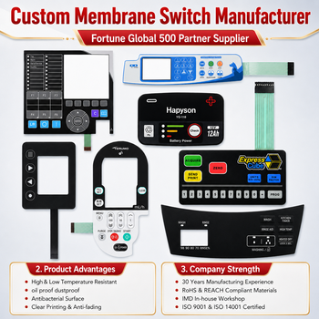
5×4 Matrix Membrane Switch with FPC Circuit
High-density 20-button panel with copper FPC traces for low trace resistance (<1Ω) and SMT LEDs.
- Circuit TypeCopper FPC
- Tactile Force300g ± 30g
- ConnectorZIF / Female Housing

A complete engineering guide on matrix layout architecture, tactile dome forces, IP67 sealing, and global OEM sourcing trends by Dongguan AXRU Electronics Co., Ltd.
Understanding the electrical physics, pin-saving topology, and layered mechanical construction behind reliable Human-Machine Interfaces (HMIs).
When designing modern medical devices, industrial controllers, automotive cockpits, and security terminals, selecting the optimal user interface is critical. A Matrix Keypad Button Panel stands as one of the most efficient, durable, and space-conscious input interfaces available today. By organizing momentary key switches into an intersecting grid of X-axis rows and Y-axis columns, electrical engineers can dramatically reduce microcontroller (MCU) pin counts. For example, a 16-key direct-drive interface demands 16 discrete I/O lines plus ground; a 4×4 matrix switch panel accomplishes the exact same functionality using merely 8 pin connections (4 rows + 4 columns), leaving vital MCU pins available for display buses, sensors, and wireless modules.
At Dongguan AXRU Electronics Co., Ltd., our engineering team evaluates every Matrix Keypad Button Panel design through a multi-layer Design for Manufacturability (DFM) lens. A typical high-reliability matrix switch assembly consists of six engineered layers:
A common technical challenge in matrix keypads is "ghosting" or "masking," which occurs when three buttons in a square configuration are pressed simultaneously, closing an unwanted circuit loop and sending a false input signal to the controller. To solve this for mission-critical applications, Dongguan AXRU Electronics Co., Ltd. integrates surface-mount Schottky isolation diodes directly into the FPC matrix circuit or designs customized contact geometry to ensure true N-key rollover protection.
Explore our field-tested Matrix Keypad configurations. All parameters including dimensions, key count, tactile force, backlighting, and connectors are 100% customizable.
High-density 20-button panel with copper FPC traces for low trace resistance (<1Ω) and SMT LEDs.
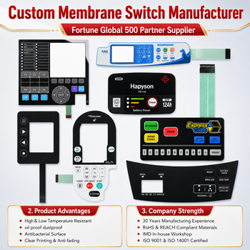
Combines three-dimensional soft tactile silicone keycaps with an underlying conductive matrix circuit sheet.
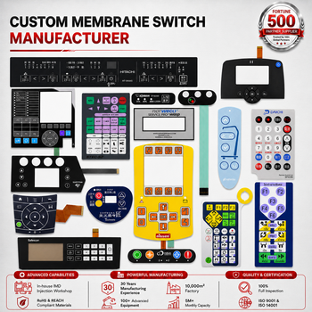
Features four-leg stainless metal domes for crisp tactile snap feedback and over 1 million switch cycles.
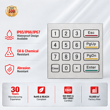
Heavy-duty 304/316 stainless steel faceplate engineered for outdoor fuel pumps, kiosks, and ATMs.
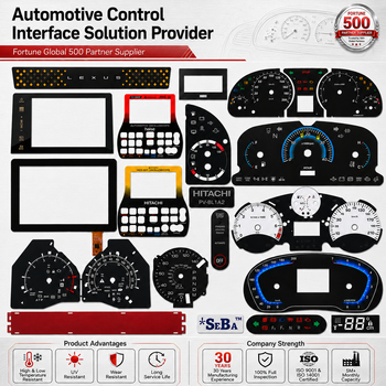
Precision translucent screen-printed graphic faceplate tailored for backlighting consistency and thermal tolerance.

Cleanable, moisture-resistant matrix keypad panel customized for commercial kitchens and appliances.
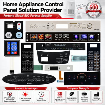
Perimeter gasket sealing design preventing ingress of water spray, airborne dust, and industrial oils.
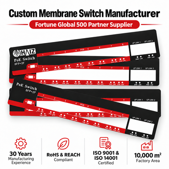
Custom graphic faceplate layer with precise Pantone color matching and laser-cut display cutouts.
Key technological innovations reshaping how OEM buyers specify and procure Matrix Keypad Button Panels for next-generation hardware.
Traditional matrix keypads relied on discrete point-source SMT LEDs, causing hot spots and uneven legend illumination. Global OEMs are rapidly switching to LGF (Light Guide Film) matrix panels. By utilizing side-emitting micro-LEDs paired with laser-etched optic film patterns, light is evenly scattered across all button legends and perimeter borders with a stack-up thickness under 0.8mm.
As electronic enclosures shrink, matrix signal density increases. While screen-printed silver ink on PET remains cost-effective for standard matrix keypads, high-reliability medical and military devices are moving to Copper Flex (FPC) matrix circuits. FPC enables tighter trace pitch (≤0.5mm), superior flexural fatigue resistance, direct soldering of surface-mount components, and total immunity to silver migration in humid environments.
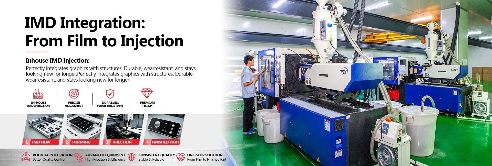
Conventional membrane matrix panels feature graphic overlays attached via pressure-sensitive adhesives. Modern automotive and high-end appliance buyers are demanding IMD (In-Mold Decoration) Matrix Panels. Through thermoforming printed films into the plastic injection mold, the graphic layer becomes an integral part of the plastic housing, delivering zero edge peeling, superior 3D key contours, and extreme chemical durability.
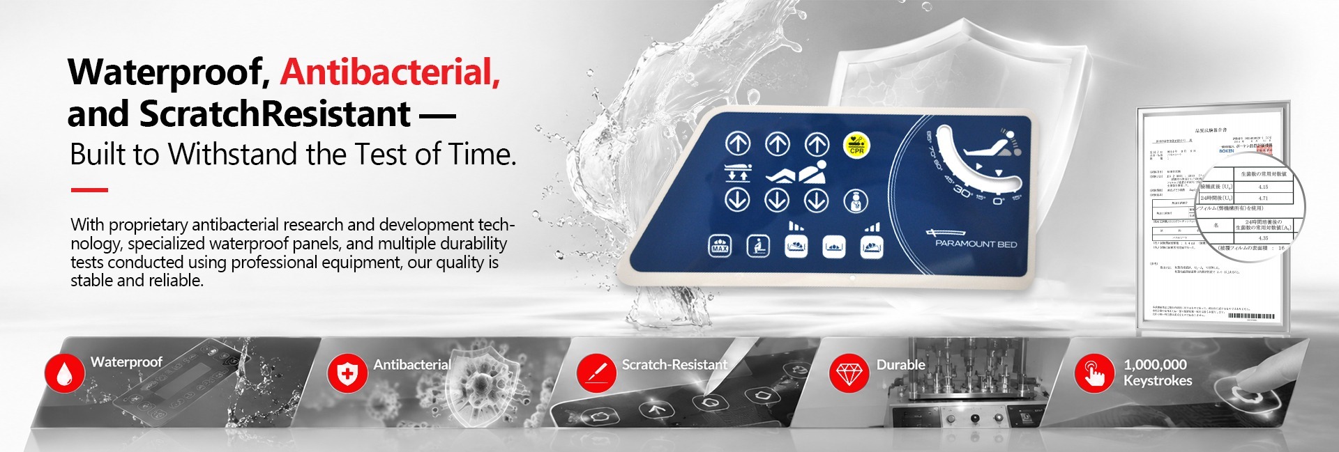
Accelerated by post-pandemic hygiene standards in hospital and public-kiosk applications, matrix button panels now frequently incorporate permanent antimicrobial coatings (such as Microban® or silver-ion additives) into the PET graphic film. These coatings actively destroy 99.9% of bacterial growth while resisting harsh hospital disinfectants including isopropyl alcohol, bleach, and peroxide solutions.
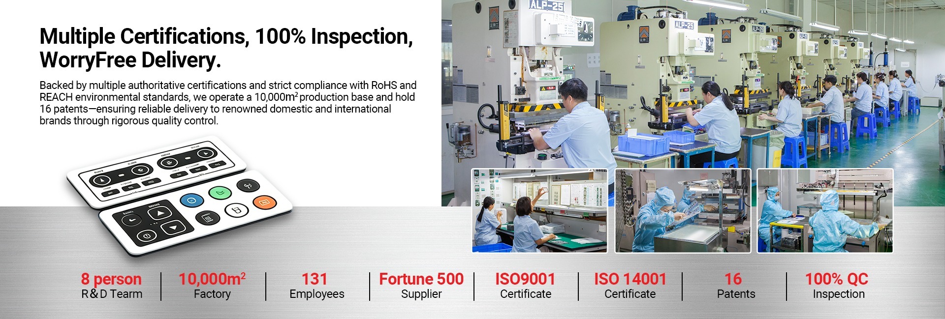
Verified by Intertek. Operated under strict ISO quality management. Every Matrix Keypad Button Panel is backed by state-of-the-art testing equipment.
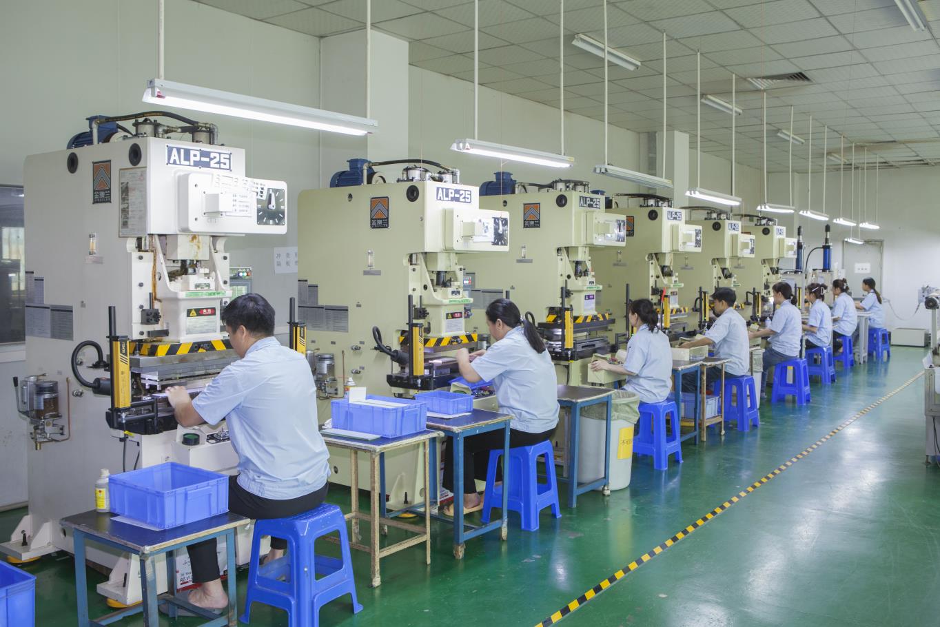
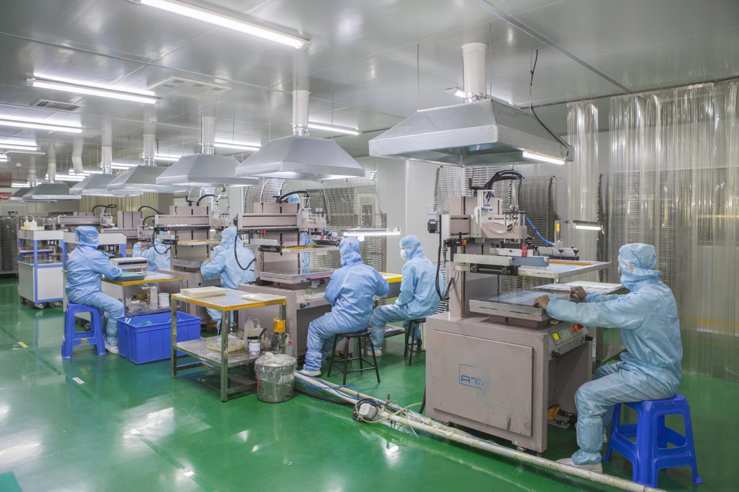
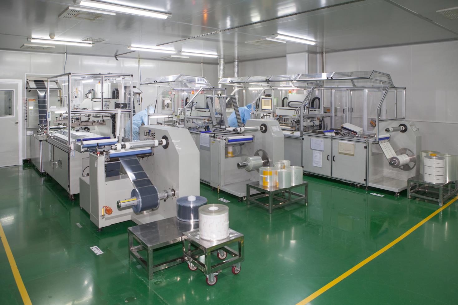
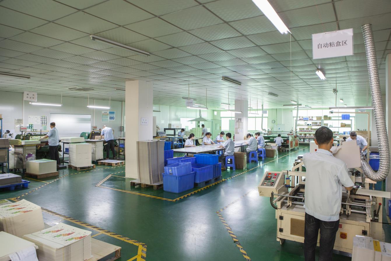
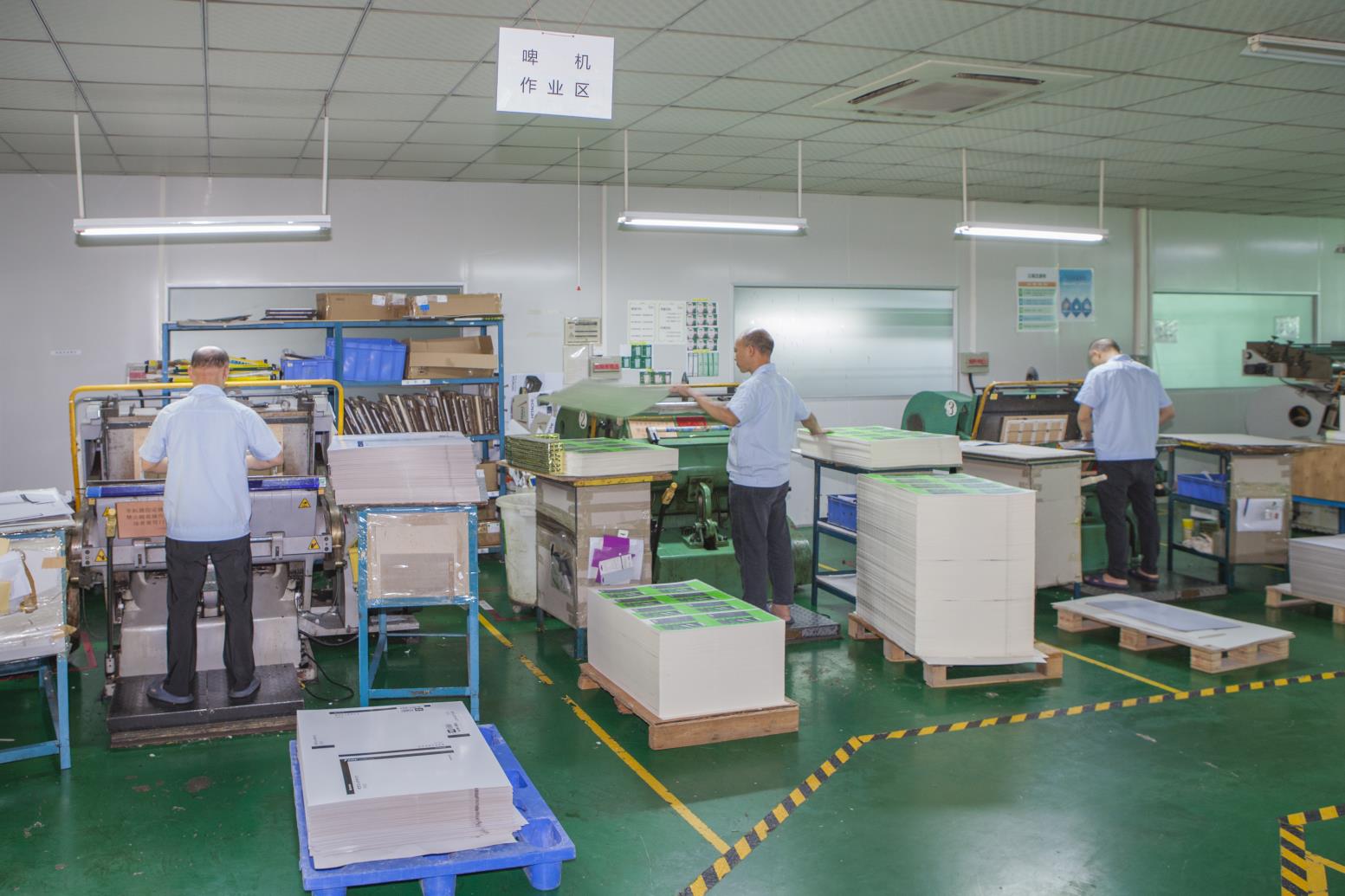
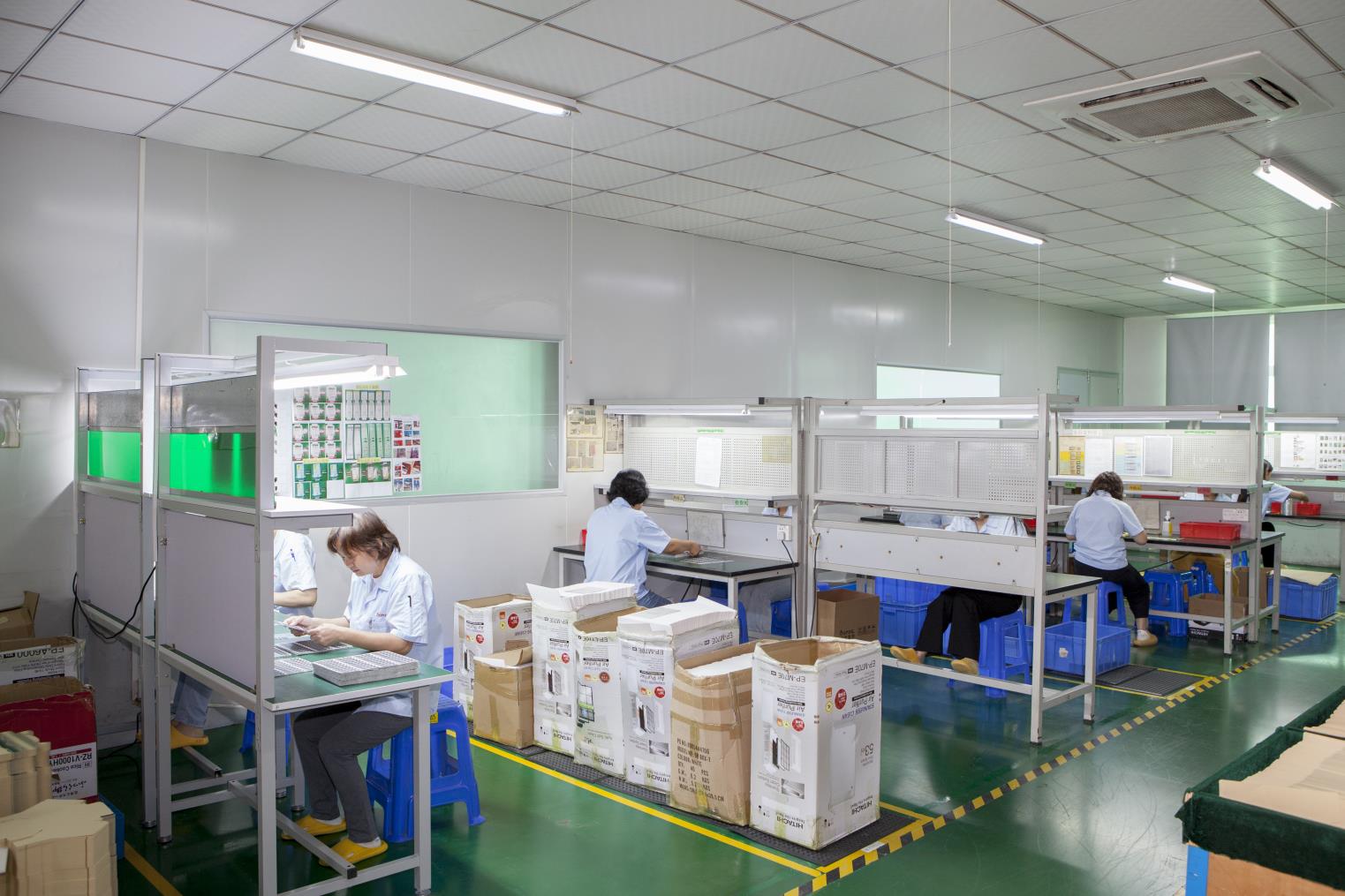
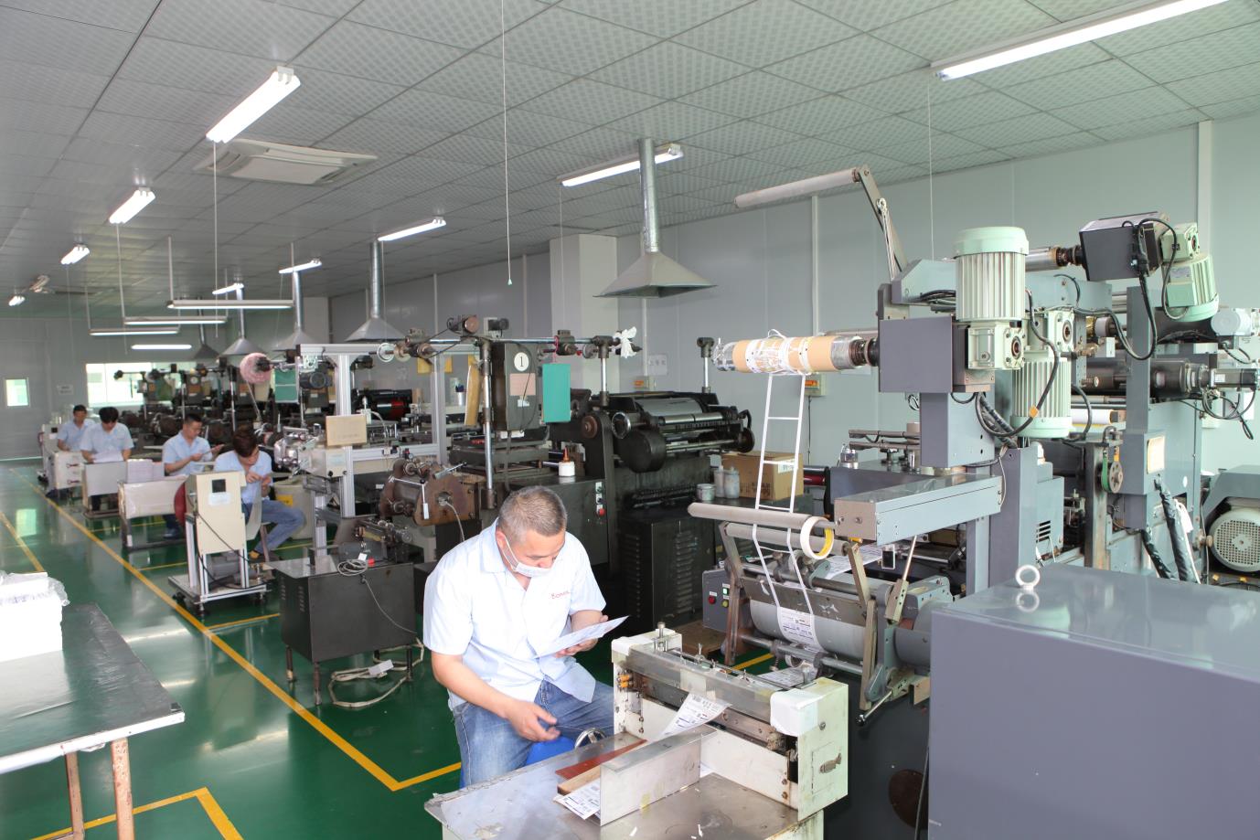
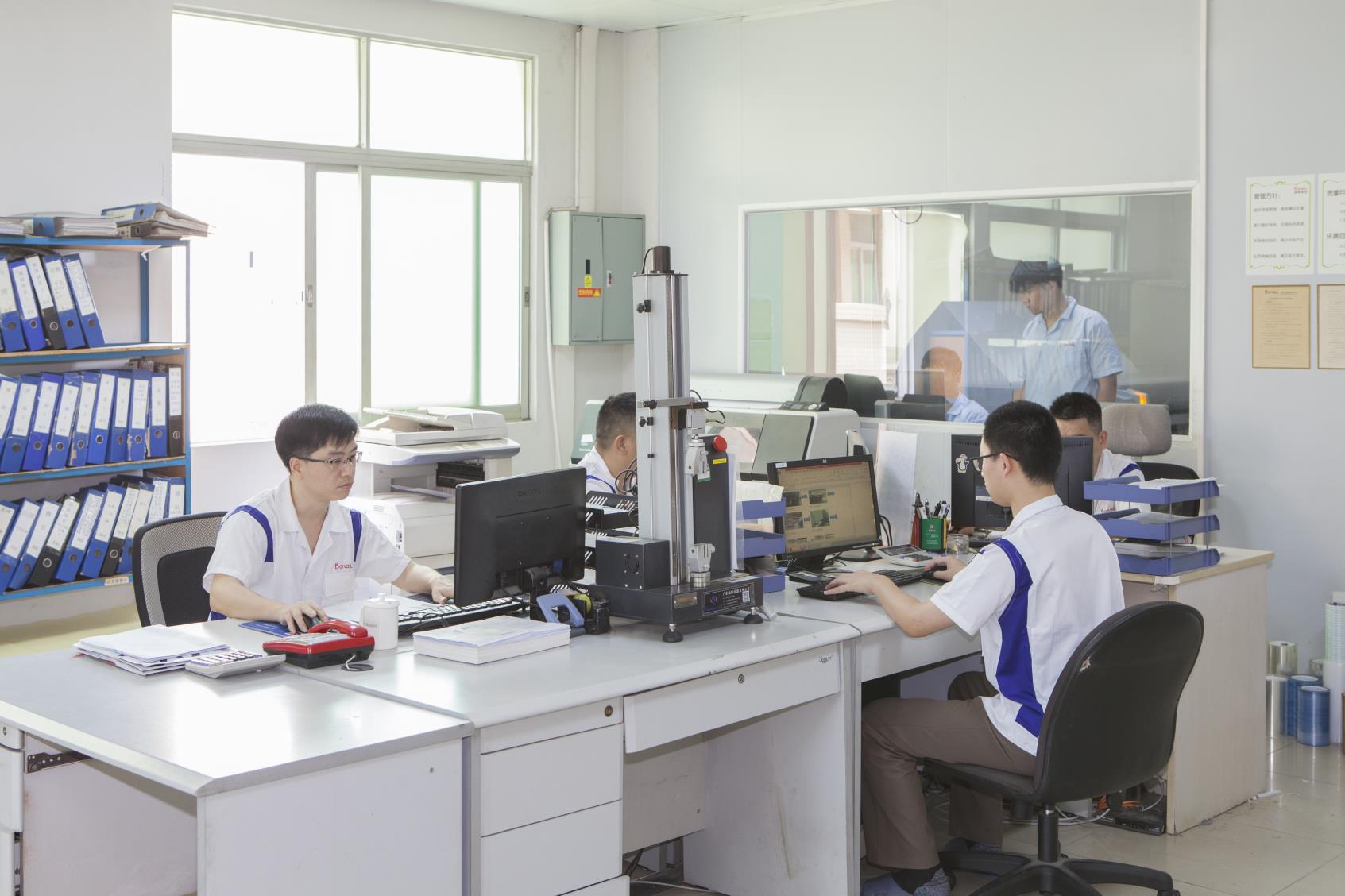
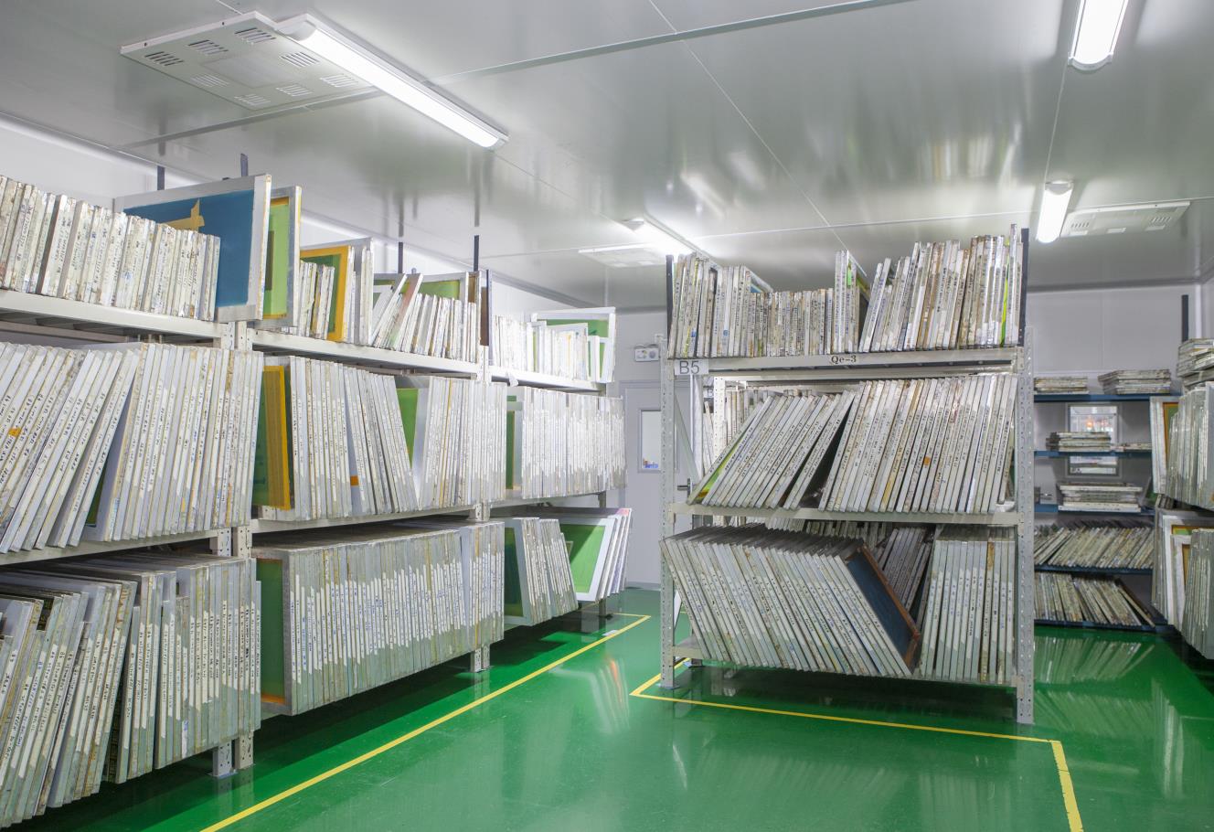
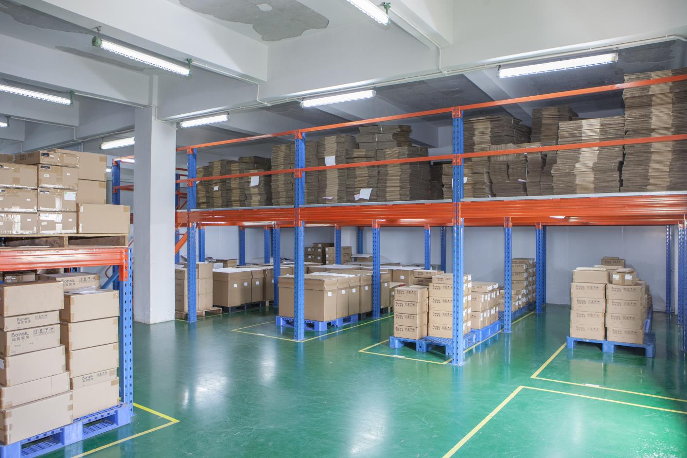
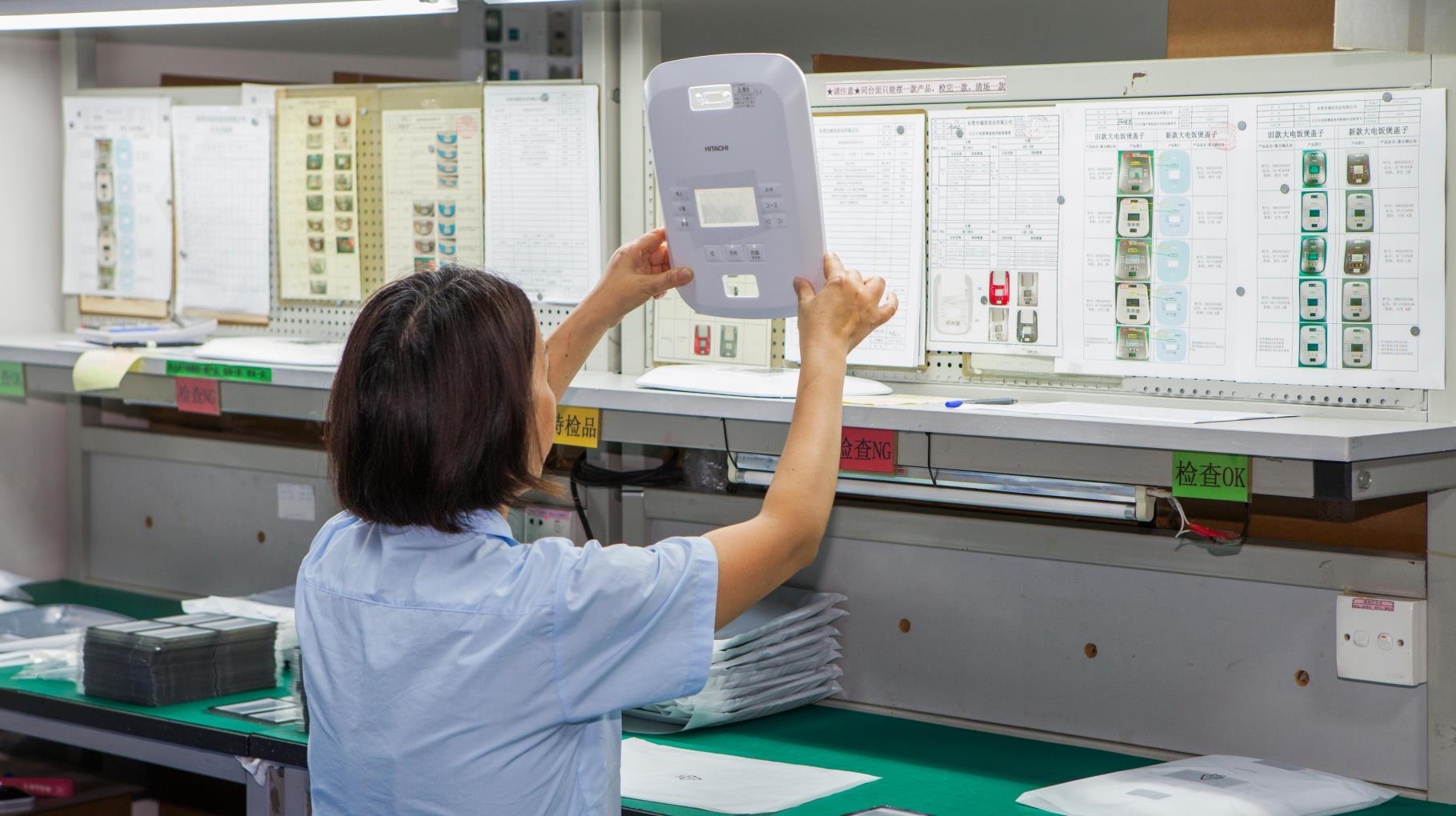
Every single matrix keypad button panel undergoes complete electrical continuity, loop resistance, shorts, and LED functional verification prior to packing.
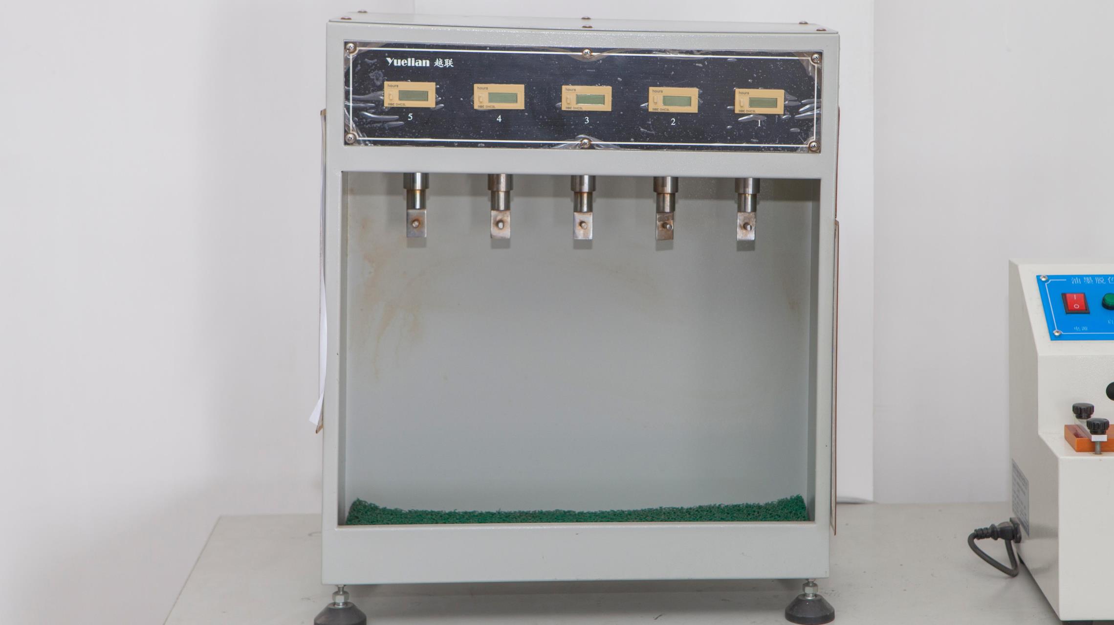
Measures adhesive peel strength and tail connection bonding forces to guarantee zero layer delamination under stress.
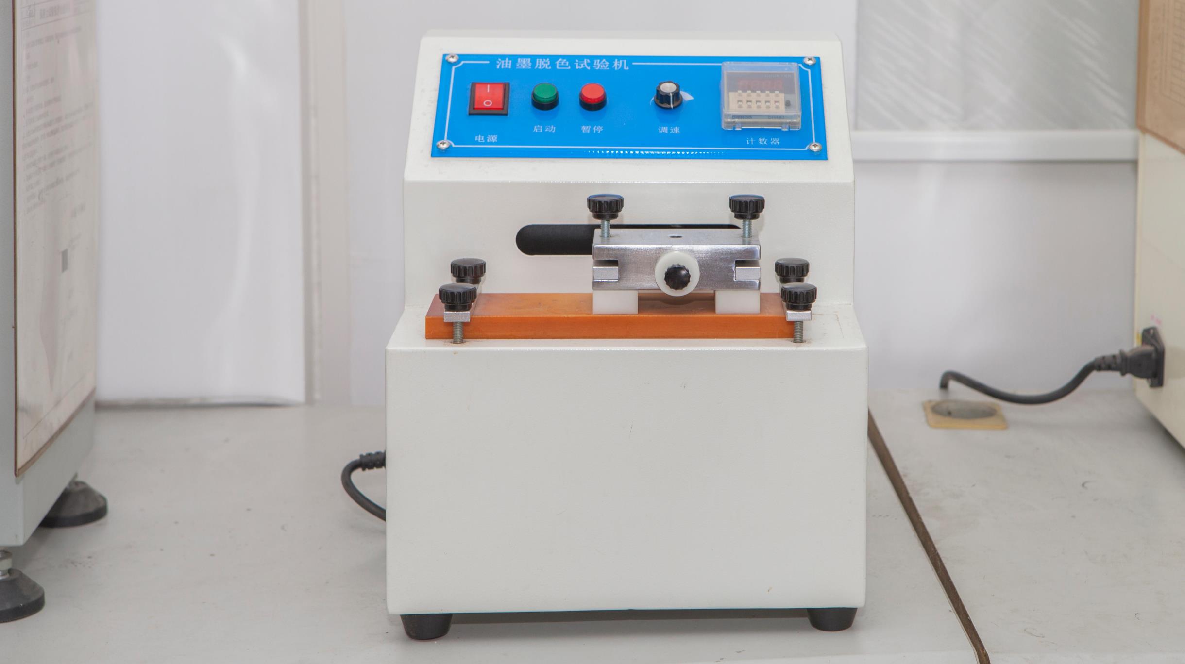
Subjects overlay legends and key symbols to rub tests with isopropyl alcohol and solvents to verify print adhesion durability.
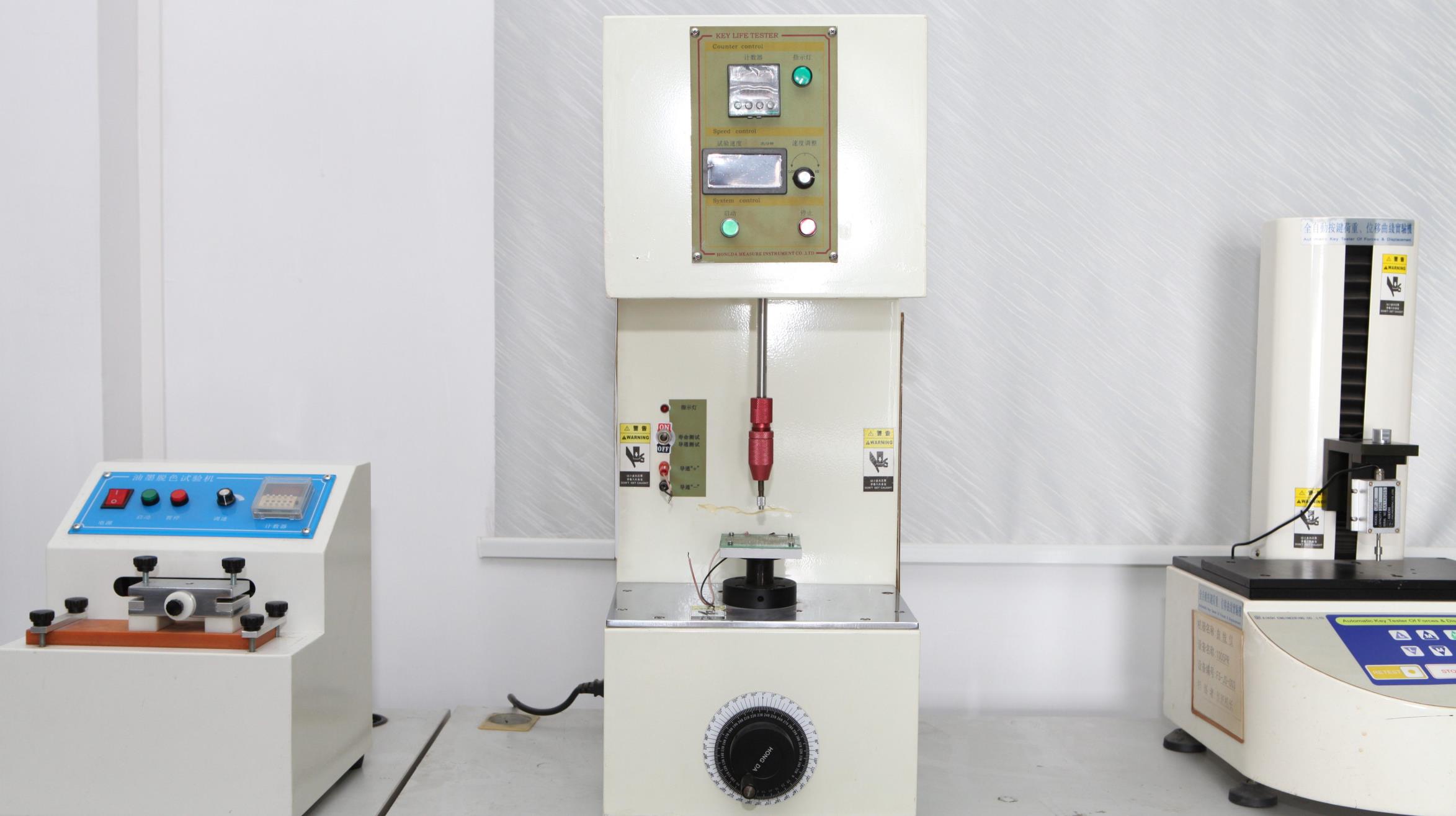
Automated pneumatic actuators cycle matrix buttons up to 5,000,000 actuations to confirm dome and circuit fatigue resistance.
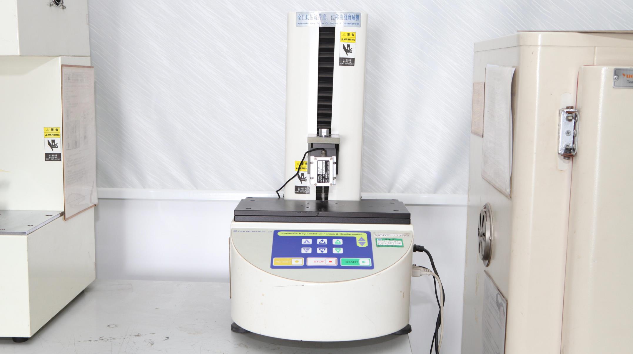
Plots precise force-displacement curves (actuation force, return force, travel distance, and snap ratio) for flawless tactile feel.
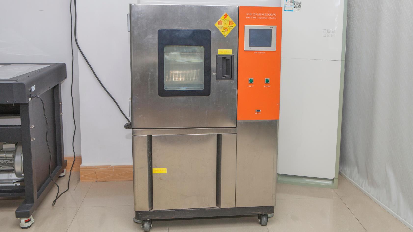
Exposes matrix panels to environmental extremes (-40°C to +105°C, 95% RH) to validate moisture sealing and adhesive stability.
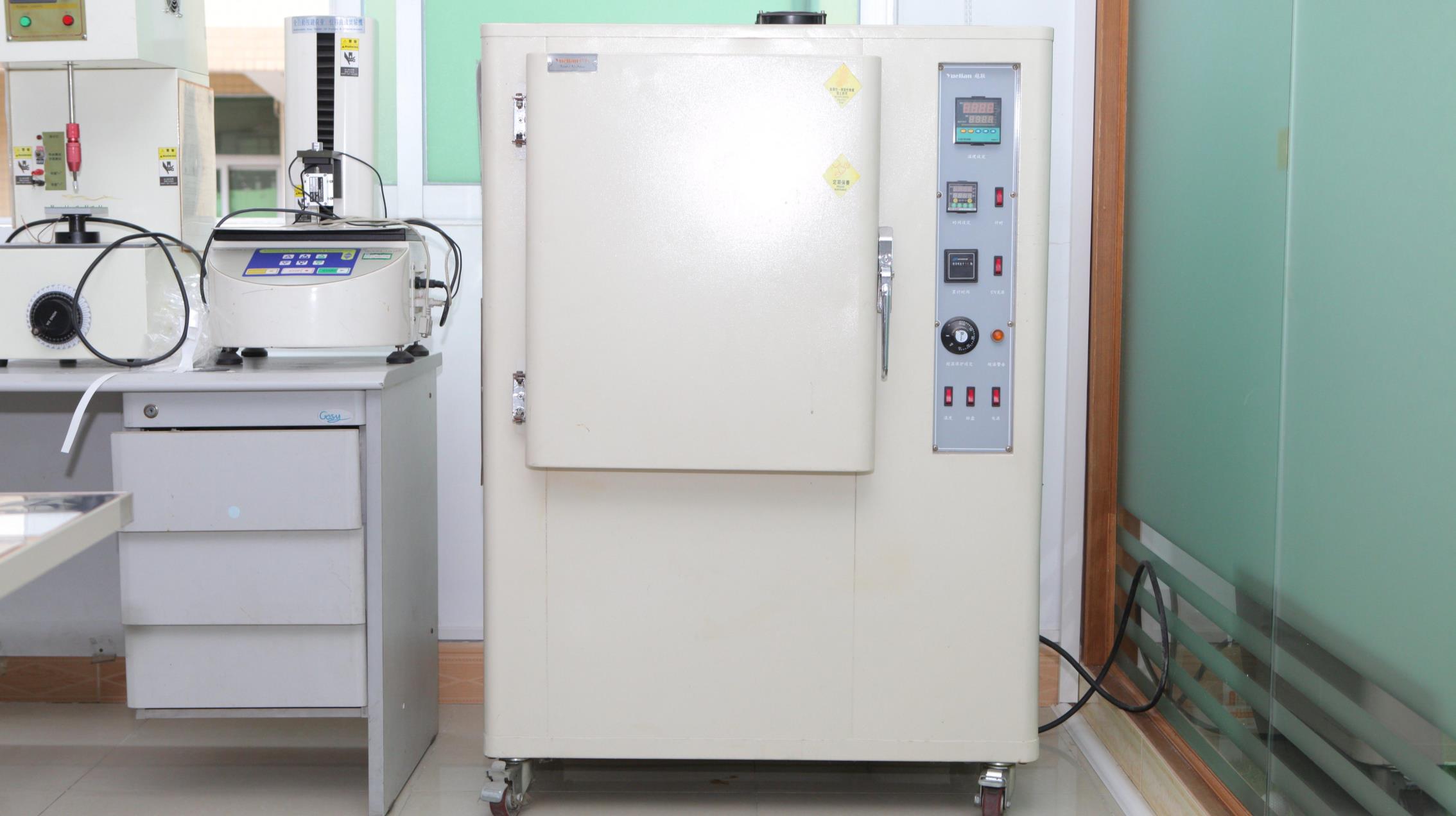
Accelerated UV radiation exposure chambers ensure graphic overlays retain color accuracy and clarity in outdoor sunlight.
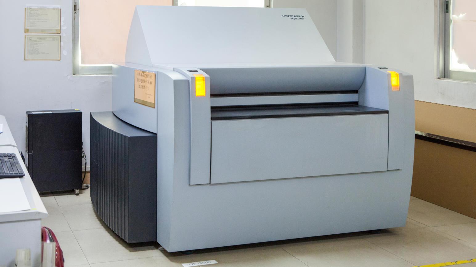
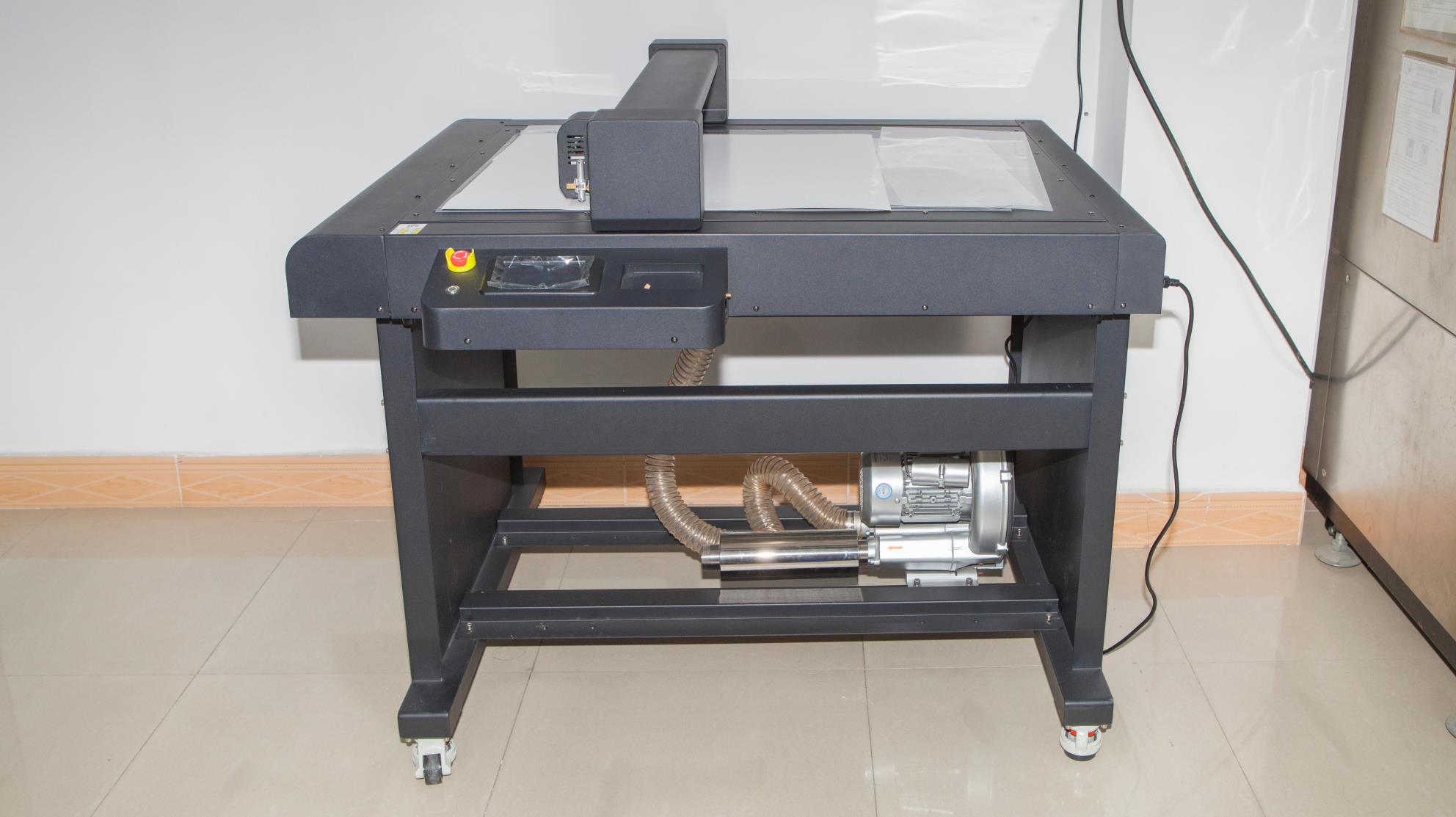
High-precision CNC prototyping cutters allow rapid delivery of functional matrix keypad prototypes within 3 to 5 business days.
Heavy-duty precision stamping presses cut complex external dimensions, internal display windows, and mounting holes to ±0.05mm tolerance.
Answers to common technical, design, and sourcing questions asked by OEM engineers and procurement teams.
A matrix keypad organizes key switches into an intersecting grid of X rows and Y columns. Instead of allocating 1 MCU I/O pin per button (e.g., 16 pins for 16 switches), a 4×4 matrix uses 4 row pins and 4 column pins (totaling 8 pins). The microcontroller scans rows by driving them low sequentially and reading column inputs. This 50% pin reduction significantly simplifies circuit routing and lowers system component costs.
Ghosting occurs when three buttons forming a right angle in a matrix grid are pressed simultaneously. Current flows through the closed switches, causing the controller to detect a phantom "fourth" button press. Dongguan AXRU Electronics Co., Ltd. eliminates ghosting by placing surface-mount isolation diodes (e.g., 1N4148 or Schottky diodes) in series with each switch on Copper FPC circuits, or by optimizing firm-ware anti-ghosting scanning routines.
Silver Flex circuits (conductive silver ink screen-printed on PET) offer the most economical solution for standard industrial keypads with trace pitches ≥1.0mm and loop resistance under 100Ω. Copper FPC (Flexible Printed Circuit) is recommended when your design requires fine pin pitch (≤0.5mm), soldered surface-mount LEDs/diodes, low loop resistance (<1Ω), extreme vibration durability, or high moisture/humidity resistance to eliminate silver migration risks.
To seal matrix keypads against dust and fluids, Dongguan AXRU Electronics Co., Ltd. incorporates a continuous perimeter adhesive ring using waterproof acrylic adhesives (such as 3M 200MP or 300LSE series). Additionally, we design sealed tail-exit channels that prevent water ingress along the flexible ribbon cable and implement embossed full-membrane graphic overlays without unsealed cutouts.
We provide three primary tactile feedback choices: (1) Stainless Steel Metal Domes: Offer crisp tactile feel, snap ratios between 40% and 60%, and 1M to 5M cycles. (2) Poly Domes (Embossed PET): Formed directly in the PET circuit or overlay layer for smooth click feel at lower cost. (3) Silicone Rubber Keycaps: Placed over metal or poly domes for a soft, ergonomic, high-travel tactile response popular in medical equipment and handheld devices.
To provide a detailed DFM evaluation and quote within 24 hours, please submit: 2D dimensional drawing (DXF, DWG, AI, or PDF), graphic artwork with Pantone color codes, circuit schematic or matrix pinout chart, connector specification (pitch, pin count, ZIF/female housing), and environmental requirements. If you only have a conceptual sketch or physical sample, our engineering team in Dongguan can reverse-engineer the specification for you.
Send your drawings or technical requirements directly to our engineering team at [email protected]. We provide free DFM stack-up reviews and rapid prototyping.